
150W Subwoofer
Contents
Page 1 - Design
Page 2 - P3A Amplifier
Page 3 - Input filter and EQ
Page 4 - Power Supply details
Page 5 - Box design
Page 6 - Box Construction
Page 7 - PIC Micro Control
Speaker Parameters
In order to build a box, I needed to know more about more RCL 10154HP speaker, including the Thiele/Small parameters.
Rod Elliott has an article on his site of exactly how to obtain the parameters, but be warned, a certain amount of equipment is needed. I managed to get away with:
- A 14W amplifier, the TDA2030 amplifier
- A laptop, with a headphones jack connected to the amplifier
- A 10 ohm, 7 Watt resistor (5 Watt will do)
- A digital multimeter, capable of accurately reading AC voltage in the scale of 0 Volts to 1 Volt
- A speaker stand, so the driver is in free air
- A length of speaker cable
Many of us are more likely to have a laptop, or a nearby PC then an audio frequency osciallator and a DMM with low frequency measurement, and whilst not quite so ideal, it does work.
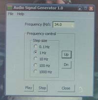
Balkishan Rohit has managed to write an easy to use, simple audio tone generater which has worked with every Windows machine with Direct X 8.0 that I have tried it with, and for Linux users it can also be emulated using WINE.
To get it, go here, and download the Audio signal generator 1.0 setup.
The importance of an accurate multimeter must be stressed. The first tests I preformed were with a DMM with the lowest AC voltage range going up to 200V. This meant the accuracy was just to 1 decimal place. My analogue MM was slightly better with the lowest scale being 0-10Volts AC, but when dealing with voltage measurements around 0.1V I had trouble reading the value from the needle posistion. So I went out an brought a much better DMM, which will read values up to 3 decimal places, and auto-scales... Pretty lucky to get one as it was discontinued and on special offer.
The Experiment
 The first set of tests, to obtain Fs, Qms, Qes, and Qts, were performed on the
speaker in free air. To get as close as possible to free air, objects must not
be any closer then 2ft.
The first set of tests, to obtain Fs, Qms, Qes, and Qts, were performed on the
speaker in free air. To get as close as possible to free air, objects must not
be any closer then 2ft.
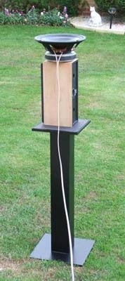
My decision was to take the experiments outside, and use an old speaker stand and centre speaker to stand the 10" driver on top of. This standing in the middle of my parent's garden would be ideal for the experimentation to begin..
Not having crocodile clips, I cheated and got away using the loudspeaker cable to wrap round the speaker terminals, which proved to be secure and reliable enough for my needs.
At the other end, the speaker connected to the amplifier via a 7 watt resistor.
Again the speaker cable wrapped round the resistor tightly enough and the amplifier's spring clip terminals held the other end of the resistor and the speaker negative side of the cable.
 The laptop was connected
to the amplifier using a 3.5mm to phono lead adaptor, the amplfier itself is a
stereo amp, but I left one output unconnected...
The laptop was connected
to the amplifier using a 3.5mm to phono lead adaptor, the amplfier itself is a
stereo amp, but I left one output unconnected...
Rohit's frequency generator running on my laptop was accurate enough for these experiments, and fortunately there was a bit of cloud so I could just about see the laptop screen, as the photo shows!
Before wiring, don't forget to measure the exact resistance of the 7 watt resistor and the speaker coil. And also fire up the downloadable spreadsheet ls-param from Rod's site, which is extremely convenient and makes these experiments easier to log and the conclusions from them easier to reach! Enter what you know, such as the above resistances now.
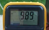 Once everything is
wired the amplifier output must be set to somewhere between 0.5V to 1V. To do
this, generate a tone above the expected speaker resonance and measure the output
of the speaker terminals. Shown left is my initial reading, and I started the
tests at 1V. This was the closest I could get. Enter this number into the
spreadsheet, and it should generate a voltage called Vref. This is what you should
see when you connect the multimeter across the resistor. If not, adjust the
frequency until you are further from the resonance, or double check you resistance
readings.
Once everything is
wired the amplifier output must be set to somewhere between 0.5V to 1V. To do
this, generate a tone above the expected speaker resonance and measure the output
of the speaker terminals. Shown left is my initial reading, and I started the
tests at 1V. This was the closest I could get. Enter this number into the
spreadsheet, and it should generate a voltage called Vref. This is what you should
see when you connect the multimeter across the resistor. If not, adjust the
frequency until you are further from the resonance, or double check you resistance
readings.
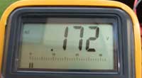 Now you can find the resonance, go down the frequency until you see the lowest
reading on the multimeter (across the resistor). This is resonance, my lowest
reading is shown on the right.
Now you can find the resonance, go down the frequency until you see the lowest
reading on the multimeter (across the resistor). This is resonance, my lowest
reading is shown on the right.
You can get an idea for why crocodile clips are handy, as I found I did not have enough hands to hold both multimeter leads and click my laptops touchpad for frequency adjustment at the same time. You could get somebody else to help, as I did, but feel free to chuckle a bit when they ask if they would get electrocuted :D
Once you have found the resonance, and entered the frequency Fs and voltage Vm at that resonance, you are now presented with a -3dB voltage (Vr), which is your reference voltage to find both Fh and Fl.
Start at the resonance, and go up the frequency. The voltage across Rs should rise. Stop when it equals Vr, this frequency is Fh. Do the same in the other direction from Fs. Where the voltage across Rs equals Vr again, this is Fl. However, if your amplifier or multimeter are slightly naff, they may drop the output/reading at lower frequencies. To get around this, when I felt close to Fl, I would measure the voltage atthe amplifier terminals and increase it to match Vs.
The spreadsheet will work out Qms, Qes and Qts for you. However, don't stop there, as my table of results show below, variations are large and I conducted 5 tests at different amplifier voltage outputs in order to obtain an average.
| Test 1 | Test 2 | Test 3 | Test 4 | Test 5 | Average | ||
| Vs | 1.01 | 0.91 | 0.80 | 0.71 | 0.61 | 0.81 | Volts |
| Vm | 0.17 | 0.16 | 0.14 | 0.11 | 0.17 | 0.15 | Volts |
| Fs | 33.5 | 34 | 34 | 33.5 | 33.5 | 33.7 | Hz |
| Rm | 48.72 | 47.04 | 47.29 | 57.33 | 25.17 | 45.11 | Ohms |
| Fh | 53.4 | 53.5 | 54 | 53 | 53.4 | 53.46 | Hz |
| Fl | 18 | 20 | 21.5 | 20 | 18 | 19.5 | Hz |
| Qms | 1.76 | 1.86 | 1.93 | 2.03 | 1.37 | 1.79 | |
| Qes | 0.29 | 0.32 | 0.33 | 0.28 | 0.52 | 0.35 | |
| Qts | 0.25 | 0.27 | 0.28 | 0.24 | 0.37 | 0.28 |
The average Qms, Qes and Qts parameters are what I would use to design the final box. But one essential parameter is still missing... Vas.
Measuring Vas
Vas requires you basically to be able to find the resonance of that speaker in a sealed box. This is where some scrap wood, glue, and nails come in handy as I had to build my own box in order to get the Vas parameter reading.
This box however went on to become my actual subwoofer enclosure for a short while as I was deciding on what type of main box I was going to build. It actually worked quite well, so was worth building!
Rod suggests that the box for working out Vas should be approximately a square of the speaker diameter. Since I wanted to make good use of my scrap wood (not a little use with lots left) I decided to go for 260mm internal dimensions. The scrap MDF I had was not very thick, 9mm in total. This would mean cuts of sizes:
- 260mm x 260mm - For two of the sides
- 278mm x 260mm - For the other two sides
- 278mm x 278mm - For the top and the bottom
Everything except the top was managed to be made from my scrap piece of mdf, except the top. The top was acutally made from a scrap piece of chipboard.
Ok, so this isn't ideal, but would be good enough as I wanted to perform the tests as soon as possible. A quick build proved my measurements were quite accurate enough to build "the cube".
Dad helped me build the case, as he wasn't doing much else and looked a little bored. He quite enjoyed making it actually, and so did I. Its also good pratice for making the final cabinet!
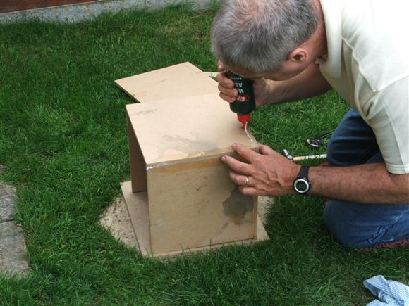
Test box construction
The whole lot was made using just PVA glue and panal pins (aka small nails). This actually proved quite effective and after a few hours of drying time, I screwed the speaker in place, depressed the cone and noticed there was quite a good amount of air pressure behind it.
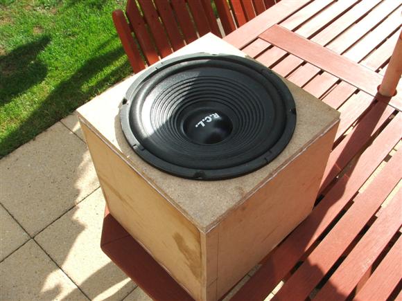
Test box with the speaker fitted and ready for testing!
The experiment is quite easy, just a case of connecting up the speaker like before to my TDA2030 amp and my laptop, with the multimeter across the 7W resistor.
The speaker, when testing in the box was not placed as shown in the photo, but rather upside down. This is how Rod's spreadsheet is designed to calculate the box volume, by adding together the total volume of the cube, the baffle cutout and the speaker cone. It is quite approximate in a sense, but most likely good enough.
Once all the measurements were complete, I then used various frequencies to determine the resonant frequency. 82.5Hz was my find (that is where the voltage was the lowest across the 7W resistor). The calculation can then be performed and a Vas of 92.96 Litres is produced.
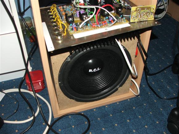
Quick system testing
Using the box for measuring the Vas, I decided to mount the speaker properly and use some speaker terminals I had for cabinets so I could hook up the speaker to the amp (which would be external) and see how it performs!
Test box in temporary use!
Believe it or not, even in that position, the performance was quite acceptable!
I would never keep it as a pernament solution, but for the time being whilst I decided on a case design and built it, this test box coped well :)
Box Choice
LinearTeam have created an ideal program to aid in the construction of speaker boxes, called WinISD. Actually there are two versions of this freeware software, WinISD beta and WinISD Pro Alpha. You can get these here
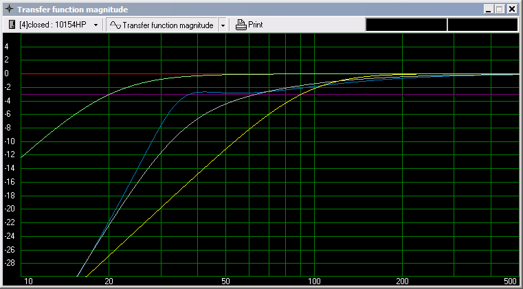
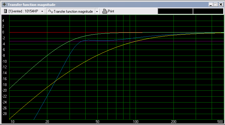
Box Responses
The image above shows the response curves of my sealed enclosure used for testing above, an extended bass shelf ported enclosure with one driver and the same enclosure with two drivers connected in isobarik form...
| Sealed Enclosure | Volume: 16.00 litres One Driver |
| Extended Bass Shelf (-3dB) | Volume: 38.20 litres Tuning Frequency: 34.52Hz One Driver |
| Extended Bass Shelf (-3dB) with two drivers | Volume: 38.20 litres Tuning Frequency: 34.52Hz Two Drivers (IsoBarik) |
| Sealed Enclosure with Linkwitz Transform Filter | Volume: 18.03 litres One Driver Linkwitz Transform (f0=89.21 Q0=0.70 fp=20.00 Qp=0.71) |
There are a few things to note here. Firstly, my current box obviously is not the best performance I can get. The ideal situation would be to use a sealed box of more or less the same size with a Linkwitz Transform Filter in order to get the kind of response shown by the light green line.
Using the Linkwitz Transform circuit would get me response down to 30Hz or lower, but the problem is my speaker and enclosure are almost -20dB down at 30Hz currently, and this kind of boost would require nearly 7 times the power (or 6.66).
As you know, I only have an 200W power amplifier, and the speakers' handling power is just 150W. My speaker has an SPL of 96dB. To reach an average listening level of 100dB I would need 4 watts of power.
Using a method similar to Rod's Linkwitz Transform Project, I have the following situation:
| Power | 4W | 8W | 16W | 32W | 64W | 128W | 256W |
| Boost | 0dB | 3dB | 6dB | 9dB | 12dB | 15dB | 18dB |
From this, to get down to 30Hz, I would need over 256W of power when listening at around 100dB :o
In IsoBarik configuration and in a 40 litre box, things improve as at 30Hz I am a better -13dB down. This corresponds to something like 80W of power, which becomes possible - but what if I want to go to a level more than 100dB? There is not much headroom. Being in IsoBarik configuration too means I would need two drivers on the amplifier. As I cannot parallel them (as that would be a 4 ohm load) I would need to connect the drivers in series, giving a 16 ohm load, which reduces the amplifiers output to 120W. Ok, I "could" push a higher voltage into the P3A (+/-42v) to re-obtain 200W, but this would need a different transformer, filter caps and changes to my pre-regulator too.
I could set the fp of the Linkwitz Transform circuit higher, say 30Hz and this results in the maximum gain of about 10dB. This puts me at requiring, say, 40W of power, however the response of the ported IsoBarik enclosure is not far behind...
IsoBarik and transformed box responses
In this plot above, the yellow curve is a 40 litre sealed enclosure, with an IsoBarik driver configuration. The green curve is this configuration transformed with an fp of 30Hz. The blue curve is as before, the Isobarik configuration in a ported enclosure with a -3dB bass shelf.
Looking at these curves, I decided that I would go for the ported option. I have my 8-band equaliser which can provide cut and boost of +/-14dB at its centre frequencies without any trouble, and I could use this to transform the subwoofer where it is needed. There will be a certain amount of room gain at lower frequencies anyway and I personally feel that the ported enclosure will give me the desired response once I get the sub into position and fiddle with the equaliser until I am happy with it! :)
Since I can't hear 20Hz very well anyway, and hardly anything extends below 30Hz, chances are I will use my 20Hz and 25Hz controls to cut these frequencies in order to remove power requirements. To get 30Hz, 9dB of boost ought to do it ;)
My box would need to have a volume of 38.20 litres. This represents a size of around 30.5cm x 32cm x 53.6cm. Volume taken by the speaker rear and the blocks used to hold the case together inside would adjust this size a fair bit.
My biggest concern was now that I had an IsoBarik configuration... how was I going to hide the ugly back of a woofer perturbing out of the box side?
I found some IsoBarik configurations here.
Whilst they deter you from IsoBarik, I am going for IsoBarik for the right reasons...
- I have two equals drivers (just need to repair one)
- I have enough power (just) or can add more in time with a bigger transformer etc...
- I used WinISD to actually see what benefits I would get from this configuration, rather then go for it because it was recommended!
I used this site to look at the various IsoBarik configurations. The conclusion is, basically, that they recommend the 'Clamshell' approach. The trouble is, whilst this will be fine in a car boot, in a bedroom, it is just ugly. However, I did see this example.
The speaker still sticks out a lot at the bottom, but it is an improvement. My design would be similar to this, except not as tall, or big, and have an amplifier on-board. Since mine is ported too, I will stick the port on the front...