
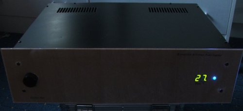
My P3A 5-channel power amplifier.
I suggest reading about the rebuild first. Information below is for reference purposes.
Contents
Page 1 - Idea and circuit choices
Page 2 - P3A Amplifiers
Page 3 - Crossover and Surround Channel Amps
Page 4 - Power Supply details
Page 5 - Testing
Page 6 - Improvements
Initial idea
As part of the plan to build myself a high quality stereo system capable of great sound, power and features I decided to build this power amp, capable of running a 4 channel setup for PC, DVD, CD, Phono and Radio use.
This project actually began to take shape around mid 2004, but these pages are now revised to reflet the changes and evolution of this amplifier over the years. A few of its original components and design features, but since its early days over 80% of it has been re-designed and rebuilt as I have found myself pushing my expectations of my work higher as I learn and experience more electronics.
I didn't realise exactly how much I would end up spending in the end... as although (as you will find during this article) I got some great bargains off ebay, I still had to do long orders for parts to several different stockists to get all I needed - not to mention the re-ordering and re-building over the years. Certainly the cost of this project ended far greater than expected, but providing you plan to design the project well, make everything work first time then this actually wouldn't be a too expensive project to build and maintain. Maintenance itself is very little in fact - in between improvements and rebuilds this amp has run without faults for months on end.
Choosing the power amplifiers:
Front amplifiers - ESP Project 3A
It took me a while to decide on what power amplifiers to use. I had set my heart on building what is referred to as the P3A (or project 3A) from ESP (Elliott Sound Products). Rod Elliott is the designer of this amplifier, which is capable of brilliant sound and recommended by many constructors.
The ESP site is in fact fantastic and many of my projects are work from the site, however the sites existence depends on the sale of PCB's and if that is reason enough, the PCB's are good quality (i.e. better than anything I could manage) and you get the benefit of saving time and effort and the reasurance that you have a good working design to build your project on.
I must confess though, the initial amplifiers in this project were built on my own PCB's. I did buy one P3A board which became soldered up and now resides in my subwoofer.
These PCB's are mostly based around the artwork of the ESP ones, but with modifications for my components and having the (essential) fuses external to the amp in order to fit them to my heatsinks. Each PCB contains two amplifiers, and there are two PCB's, which can provide a stereo 60W into 8 ohms amp, or be bridged into 8 ohms to provide beyond 100W.
However, whilst the performance of these was very good, I was always under the thought it could be better. This was due to the boards being home-made, the fuses being external (meaning quite long, and messy, power leads) and the heatsinks being a bit too small.
As part of the recent rebuild, I switched to new components using all put onto Rob's proper, and now higher quality, P3A boards.
For more details, follow this link to see Rod Elliotts' article on the P3A amplifier.
Rear Amplifiers - LM3886/ESP Project 19
I grabbed the LM3886's off ebay at a good price and I thought these would be ideal for the rear channels, certainly high enough fidelity for them anyway!
The LM3886 is a 68W integrated single chip amplifier. This basically this means that there are not many components needed to build a 68W amplifier, much like other integrated amplifiers elsewhere on my site.
Unlike most of my projects with single chip amplifiers though... the design of this one is not based entirely off the typical application in the datasheet.
Instead my work has been based on the work Rod Elliott has performed with his LM3876 design.
Again it is a very simple and good design. Rod has based his article on the LM3876, which is similar to the LM3886's I have, but with slightly less power (50W). The article is here and provides a very good amount of detail to allow someone to easily build this power amp. I have had no trouble myself (so far).
There is a slight difference, which is described in his project and that is an extra connection is needed for the LM3886. My PCB design includes this so all should be ok but it is a useful fact to note. Again, do not ask for my PCB design.. it would be unfair for me to release them when PCB's can be brought from the site.
For common use into rear speakers the LM3876 will be absolutely fine. I only got 3886's due to them appearing on ebay.
Centre channel amp?
I currently have no centre channel amp - and nor do I plan to at this present time. The intial plan was to have a centre channel amp, but I lost interest - especially because in my opinion, home cinema systems actually sound better without them, particular with music and having my front speakers quite close together.
In the early stage of the design, I did implement a TDA7293 amp on a PCB.
Apparently the TDA7293 is quite a cheap and common amp. Another ebay bargain (I actually got 5). These chips claim to give 100W (!) from 100V. Whilst I will be using +/-35V I'm sure these will give around 60W which is certainly enough for a centre channel amplifier and the quality should be more than adequate.
However, initial tests were unsucessful though - probably down to a solder error, PCB design error or schematic mis-read, and when testing this amp out I lost my test speaker to a very high frequency sound which caused the coil in the poor thing to melt and weld to the magnet!
I would normally have fixed the problem and try again, but I lost interest in it because it was a bigger amp than the LM3886 with no benefit, I had no centre speaker and the heatsink I ended up getting probably wouldn't have coped with another amp anyway.
Other components
The original design had a fan controller and fans on each heatsink, and the fan controller was basically Rod's design I had used with success in my much earlier first design of my TDA2040 amp. The project number on Rod's site is P42 - named Thermo-Fan, and this works using normal retifier diodes (cheap), with pretty good accuracy too!
Over time, I ditched this for a micro-processor implementation - which was during a time where I found programming microchips very interesting. This became a very good solution capable of monitoring each of my amps to a 2 digit display so I could see actually how many degree Centigrade my amplifier's were running at, which was a learning experience! But more on that later.
To control my power on process a bit too, this microchip solution handles speaker muting, and I have a soft start circuit, also from Rod's site, to relieve the stress on the power supply components at power on.
There are also some op-amp buffers on the input which allow me to control volume levels to the front and rear.
In time, I also plan a clipping indicator - I have some nice speakers now and knowing when I push too hard might be useful!
Thats about all that can be said about the initial ideas. The next page gives more information on the construction of the power amplifier.