7.1 channel Hi-Fi microprocessor/PC controlled Preamp
I suggest reading about the rebuild first. Information below is for reference purposes.
Initial idea
Having a 5 channel power amplifier of suberb quality - I ran into problems when it came to selecting sources for the preamp itself and controlling the volume for 5 channels (6 when you include a subwoofer too!)
Some sources have volume controls, like my DVD player which has a simple volume control of 1-20. This however is not adequate.
Analogue solutions?
Many DIY hi-fi preamps are naturally built as an entirely analogue solution, such as the ones Rod Eliott provides on sound.au.com.
For stereo preamplifiers, this is quite a simple solution, as dual potentiometers for volume are easy to find and cheap, and so are double pole input selection switches.
When you expand beyond the simple two channels is where problems are hit. Sure you could spend lots of money on an 8 channel pot, and get some special input selection switch, but there is another solution.
Digital?
Look at the commerical market for home cinema recievers, amplifiers and high end preamps...
Notice that they all have some form of digital control, of the volume, input selection etc. Many also have custom digital electronics to interfere with the sound for special EQ too, however, this was not my aim.
I never thought I'ld be building a preamp that uses some form of digital control... let alone one that can currently be controlled remotely from anybodys average Personal Computer. The initial spark for this pre-amplifier was generated when I saw Mark Hennessy's design.
Needing a good idea for an asessed computer science project too, I decide to build a preamplifier, using a suitable microprocessor.
Microprocessors - are you mad?
I used to think anyone who managed to include microprocessor control into their projects were some sort of mad people who were really really clever.
Whilst using microprocessors is certainly not for less capable programmers amongst us (i.e. those who have never programmed before), those who have had a bit of experience will most likely have the ability to program a simple embedded microprocessor system.
I say simple. Yes I mean it. That doesn't make this project simple at all - it was difficult because I really did throw myself in the deep end!
So yes, I'm quite mad in that sense that I purchased some microchips for this huge project, but as I start writing these pages, I have a very successful system. For beginners, start with something a little more simple!
I did some research, and I found out that the PIC micro is the most popular type of embedded processor to purchase and program.
Doesn't that mean you need to use Assembler language
Not really. PIC assmebler is one of the easiest to learn. But that is not to say it is easy, for beginners it certainly will not be! One of my university projects involved using PIC assmebler to make a PIC processor control several motors - a stepper motor, a servo motor and a DC motor, which was connected to a rotary encoder. Of these, we only got the stepper motor operating fully. The rotary encoder on the DC motor and the servo motor were very difficult to do at the time.
So, how would I program this preamp, with all the stated requirements below?
Well... using an alternative to assembler... C
There are some free C compilers which have limitations which are great for beginner small projects, but I knew mine would be large.
It did not take long for me to realise that there are some good value C compilers out there. My choice was C2C. This compiler is available for $69.95 USD, which is great value for money in my opinion. You get the compiler, plus an IDE (integrated development environment) to work on, which is a nice and simple IDE. To make things even easier, setting up a new project is as simple as running a wizard which can setup your processor of choice with all the correct configuration and generate skeleton C code ready for you to add in your own routines.
If you know C, this is great. If not, simple C programming can be learnt in a few weeks of hard study, with a good book on ANSI C. Not only would you learn C for your future microprocessor projects - but C is also a powerful language on both Windows and Unix PCs if your interested in developing your own software.
So anyway, I used C. No assembler was actually involved - though my basic knowledge of assembler was used at points.
Pre-amp requirements
The important part. What did I actually need (want) this preamp to do? Well a list is below:
- Control 8 Channels of volume
- Select a number of inputs - of which one would be 7.1 surround and the others would be stereo, with simple internal halfer matrix surround sound decoding.
- LCD information display - such as volume level in dB, and the name of the selected inputs
- Control of other devices - using 12V triggers to power up the sub-woofer etc...
- Be controlled from a Personal Computer - this is the really clever bit as the whole preamp can be controlled from a GUI running on a Windows/Linux PC.
- Remeber all settings when the power is removed - analogue does not suffer from this, and there are ways to prevent digital systems from losing their settings too.
These are not easy requirments to fulfil - and they were the bare minimum achievements I wanted to make. I also wanted infra-red control, advanced settings such as individual channel adjustments and balance, custom input naming, automatic loudness and surround mode activation, input trimming for those sources that are louder than others and all sorts of other ideas my mind ran through (and that Mark managed to implement successfully). :)
Analogue Hardware
Before I go onto the digital hardware, first I must look at analogue hardware.
As you know, a fully analogue system provides the best quality possible. I wanted to keep my preamp using as little digital interaction as possible. No ADC's or DAC's were present in the audio path (in theory).
Using DPDT relays for input selection solved part of the problem. The contacts on a relay are controlled magnetically, keeping the audio path well away from any noisy digital signals.
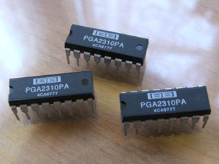 However, the digital and analogue system would meet at one point - at the volume control. Mark
had already provided some research when he did his project though and concluded that the Burr
Brown PGA2310 serial controlled volume control was a very good choice. Naturally, I decided to use
these, especially as chip samples would be free...
However, the digital and analogue system would meet at one point - at the volume control. Mark
had already provided some research when he did his project though and concluded that the Burr
Brown PGA2310 serial controlled volume control was a very good choice. Naturally, I decided to use
these, especially as chip samples would be free...
The rest of the analogue hardware involves Op-amps. This includes both preamp sections, buffers, loundess, surround sound decoding, mixing and tone controls.
Not quite having the knowledge to design these analogue systems myself, I used a combination of Mark's designs, and projects from Rod Eliotts website.
Main audio path
Since my experiments with Rod's preamp versions failed to work correctly with the PGA2310 volume control, my final design was to use for the most part the exact same design as Mark did.
For completeness it is below, but the original page is here and credit is given to Mark for his superb design skills. Unless you know what you are doing with opamp design, I suggest you also use this exact same circuit before and after the PGA2310 also.

Click to Enlarge
Construction is not too critical, except I would suggest you do not use stripboard or similar for this circuit, and when desigining a PCB layout to pay particular attention to both analogue and digital ground planes around the PGA2310 (see datasheet).
RLY1 is for output muting and it is strongly recommended that you do include it as the circuit does make all sorts of rude noises when the power supply is switched off. This relay can be powered straight from the 12V supply directly which will remove turn off noises, but will not remove turn on noises, which is why the power amp should always be turned on after the preamp.
If you want to stop turn on clicks, the relay is still used, but activated using a delay circuit such as those on Rod Eliotts' site or Mark Hennessys' site.
Both opamps need to be bypassed. For the OPA2134, use a 100n capacitor as close as possible to the IC leads from +Ve to -Ve. Likewise use the same technique for the NE5532, except with a larger 470n capacitor. This ensures the opamps do not oscillate!
The PGA2310 also needs to be bypassed to ground using 100n capacitors and correctly oriented 100uF electrolytic caps, see below.
PGA2310 bypassing
Loudness filter
My original loudness filter was taken from a book named "Preamplifier and Filter Circuits", by R.A. Penfold (ISBN 0-85934-254-9). Since this will have a copyright on it, I am unable to re-produce the circuit here...
I did not have much luck with this loudness filter, so it was removed from the preamp. The reason why is because I found out my Mission M71i speakers were actually good enough for reproducing bass at low frequencies, plus I was about to add a subwoofer so this was all better then the speakers I used at uni were anyway. I also knew I would be adding tone controls too, which would allow more control over bass when I would need it. I could also increase the level output to the subwoofer at lower frequencies too!
Tone Controls
The tone controls used in my preamp project are taken from one of Rod Elliott's preamp designs, project 97.
This tone control circuit works well and its standard configuration allows a maximum boost and cut range of 10dB. It is unlikely I would every need more then this, and I expect most of the time I would be using the tone defeat switch which is also included in this circuit.
The only change I have made is to make U1A/B a buffer with a gain of unity, and to make it an inverting buffer, so that the tone control output amplifier brings the signal back to its non-inverted state.
For reference, the changes I made are below. The result is taken from this page and this page. The result still retains the ESP logo too, since the effort was Rod's ;)